Noise problems in circuits using 74HC595 shift register |
|
| by: Eng. Ovidiu LUCA |
|
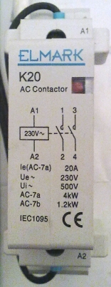
AbstractIt is often necessary to control a large number of outputs, at a relatively low speed from a microcontroller, but the number of outputs required is larger than the outputs pins available. A simple solution to this problem is a Serial In/Paralel Out shift register. Theory of operationThis is a logic circuit which accepts serial data at input, and outputs the data on multiple lines. An advantage is that most SIPO shift registers also have a serial output, which allows a daisy-chain of registers, greatly enlarging the number of available outputs. Writing software for these circuits is also simple, it resumes at output-ing a bit at a time, then generating a clock pulse, move to next bit and so on, until all bits are shifted out, then, at the end, generating a Latch pulse, so that the shift registers, latch the data from the serial shift registers to the paralel outputs (latching) registers. PracticalI was developing a modular relay board based on 74HC595, serial-in/parallel-out shift register and ULN2803 driver (8xNPN transistors) when I ran into a noise problem. The loads where contactors and some light bulbs, on the NC (normally closed) contacts of the relays, running at 220V AC. Loads where at a minimum distance of 1 meter to about 100m from the system. When the loads where not connected to the AC power grid, everything was ok, the system was running correctly. But when the loads where connected to the AC power grid, and some data was sent to the 595 register, sometimes the outputs did not change correctly. Especially when contactors were being disconnected from the AC source. |
|
|
Here is a recording of the problem. I am just making a spark (spike, noise) by connecting and disconnecting a contactor coil to the AC power line to simulate relays switching on and off. The outputs change erratically, without the microcontroller sending any data to the shift registers. |
|
The relay board had the following original schematic :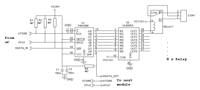
I was using decoupling capacitors, pull-up resistors, and a good power supply. I have tried:
Same result. SolutionAfter a lot of research I have reached the conclusion that the only way the data in the shift register could get messed-up is a parasitic pulse on the STORE (RCK, pin 12) of the 595 shift register, which then stores noise induced in the serial data line (SER, pin 14) by the switching contactors. So I have tried an RC low-pass filter on the STORE (pin 12). This is the new, good working schematic: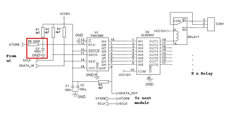
The RC filter is a 100 Ohm resistor (R5, small enough to preserve noise margin) and 100 nF capacitor (C3,small enough not to distort timings). Best results are achieved if the RC filter is placed as close as possible to the 595 shift regitster. A GROUND STAR is also a good practice: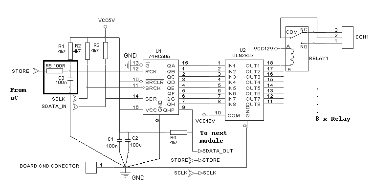
| |
|
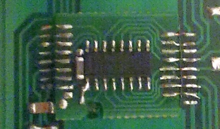
On the PCB layout is best to place the ground star center beneath the GND (pin 8) of the 595 shift register, as this is the reference (zero voltage) point for the register, and all input signals are compared to this point. |
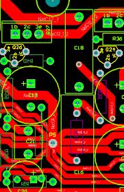
A general ground star example on a PCB layout. |
ConclusionThe RC low-pass filter, alone, sloved the problem, but a good, clean layout is also recommanded. I have tested 6 modules, starting from january 2011 and never had this problem again. |
|
Thanks to
|
|
References |
|